DueProLogic USB-FPGA Development System

ALTERA
CYLONE IV FPGA
DEVELOPMENT
SYSTEM
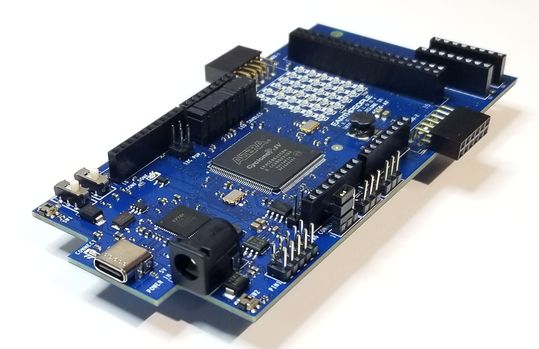
The DueProLogic is a complete FPGA
Development System designed to easily
get the user started learning and
creating projects.
| The DueProLogic makes programmable logic easy with an all inclusive development platform. It includes an Intel/Altera Cyclone IV FPGA, on board programming, four megabit configuration flash, and an SD connector for add on memory. You can create your HDL code, program it into the flash and interact with the hardware via a Windows PC. |
| This is the FPGA (Field-Programmable Gate Array) development board and runtime environment you have been waiting for to get started with programmable logic. |
DueProLogic FPGA Development System
| The DueProLogic (DPL) and its integrated development and distinctive runtime environment has been specifically designed for Electrical Engineering students, hobbyists, and entrepreneurs prototyping/developing/running projects involving logic, with the added opportunity, should it be needed for your project, of readily mating with a widely used microprocessor board, the Arduino Due, and other ARM Cortex compatibles. The combination of FPGA programmable logic and microcontroller is unbeatable in an educational student learning setting and in many other projects where each can bring its strength. |
FPGA Training
| The DPL gives learners the opportunity to have an appropriate hands-on approach when learning logic, exploring different iterations of schematic/code designs with simple uploads of the design, and the operation of those circuits with relatively easy runtime passing of project parameters and data, and an abundance of headers that can interface to external components, without having to spend inordinate amounts of time reading datasheets, designing the right combinations of gates on multi-gate chips, and building/revising/debugging/revising repeatedly… spaghetti bowls of wires and chips on multiple breadboards to connect to those same external components. With the DPL’s FPGA, projects can also more easily be attempted which rely on asynchronous, exceedingly fast, and even multiple separate concurrent logic structures operating in parallel which would have traditionally required a plethora of chip gates or multiple high speed microprocessors to implement parallel processes. Logic circuits are implemented within the FPGA at few- nanosecond gate speeds and highly parallel in operation, effectively a few hundred MHz; Microprocessors often rely on inherently slower single threaded program loops with interrupt servicing, which is typically much slower. Programmable logic is today’s technology for logic learners and implementers, replacing discrete logic chips. |
FPGA Projects
| The DPL allows the learner to be more productive and better focus on the underlying logic and integration with the non-logic aspects of non-trivial projects. Projects and solving real-world applications might involve: |
|
DueProLogic Overview
| The DPL is a complete FPGA development environment. It includes a powerful Intel/Altera Cyclone IV FPGA, High-Speed USB interface chip, Full SD Card interface connector, and 4Mb Configuration Flash (for the FPGA). The USB interface chip is an FT2232H with Dual Serial Channels. One channel is dedicated to loading the configuration Flash for the FPGA. The second channel provides a high speed interface for bi-directional communications with the FPGA. Once the configuration Flash is loaded with the users synthesized code, a reset will cause the FPGA to read the Flash and load up the stored image into the FPGA. |
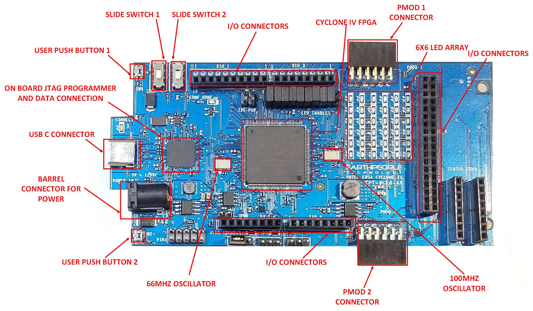
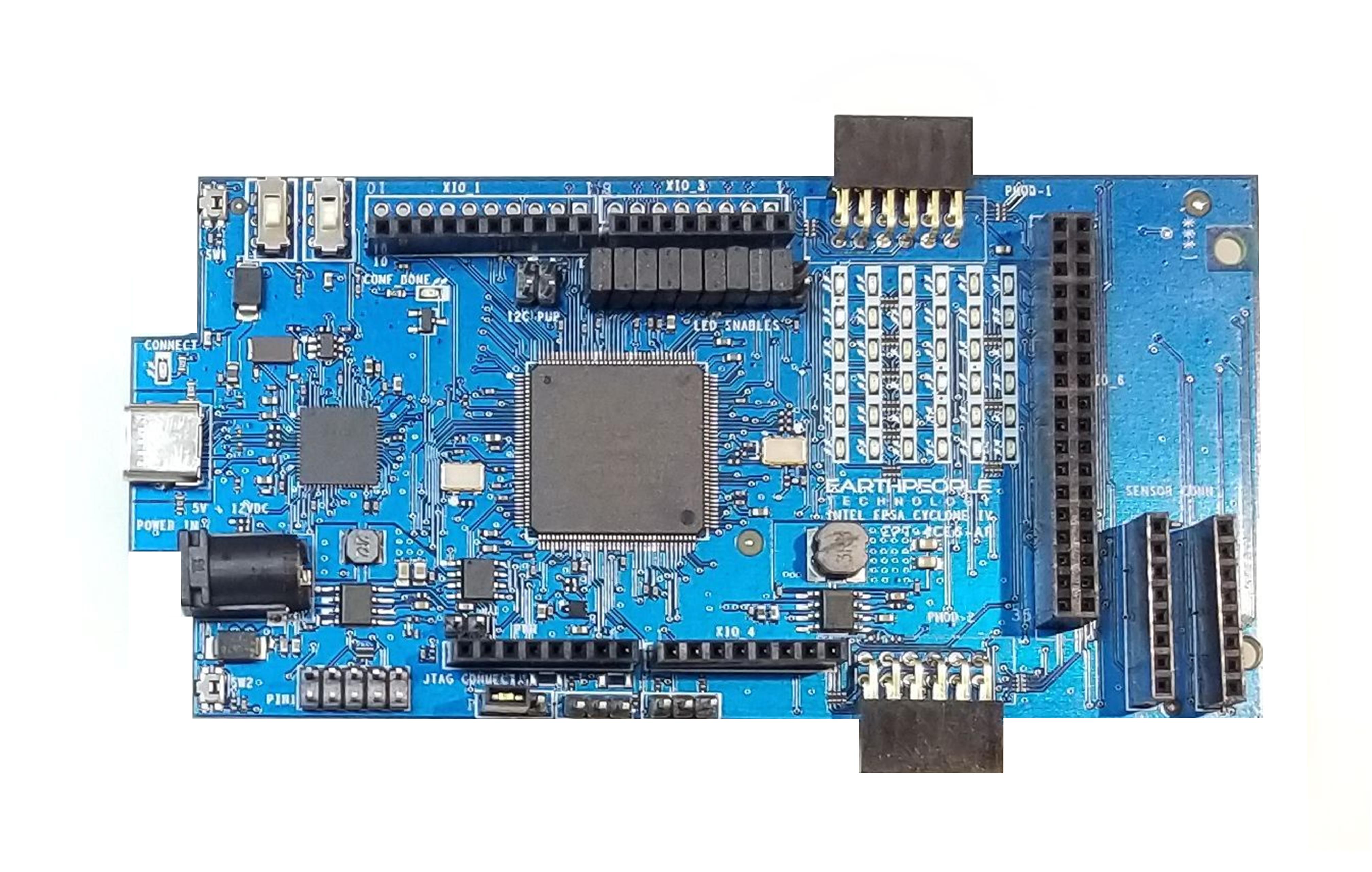
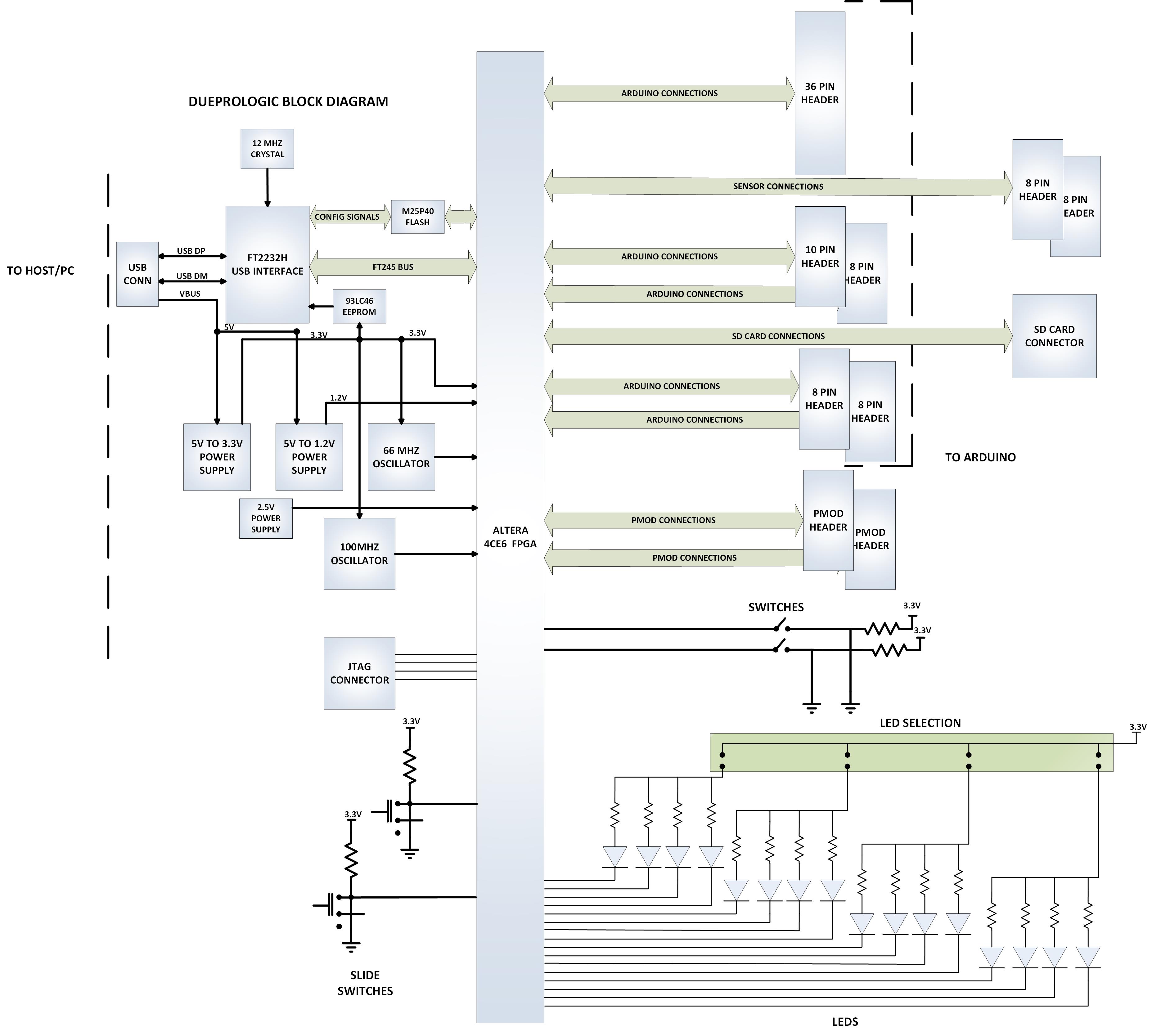
| The block diagram shows all of the parts of the DueProLogic. There are two main power supplies, +1.2V and +3.3V. The +1.2V powers the core of the FPGA while the +3.3V powers the Input/Outputs of the FPGA as well as provides power for user circuits. The DPL contains two oscillators, 66MHz and 100MHz. The 66MHz oscillator is used to provide clocking for the EPT ActiveHost USB communications core. The 100MHz oscillator can be used by the user clocked up using one of the onboard Clock-DLL modules. |
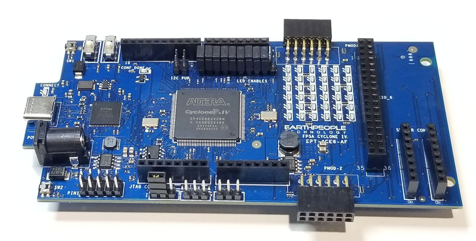
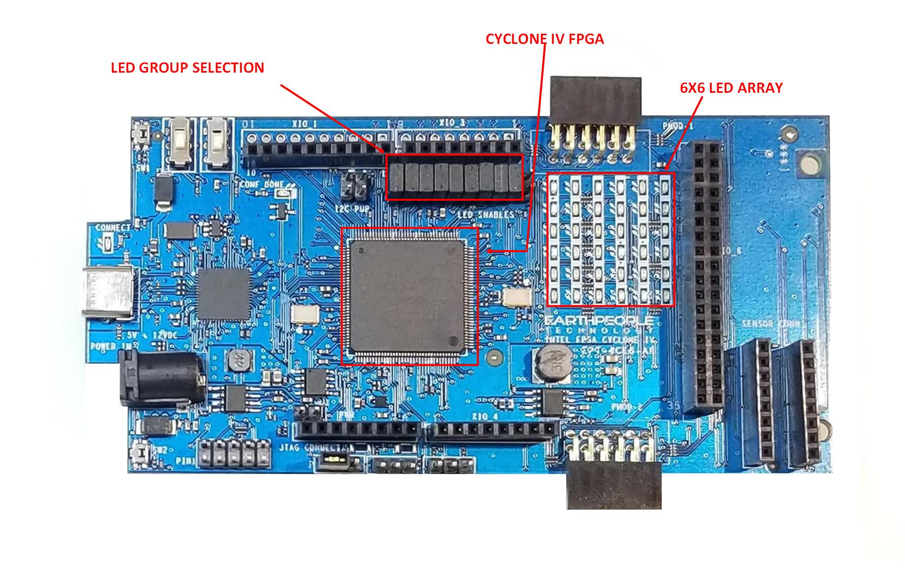
6x6 LED Array
Development Environment
| The DueProLogic includes a 6x6 Green LED array. Each LED is sinked to an individual pin on the FPGA. Each LED is current limited to 6mA. The total current consumed for all 36 LEDs is 216mAs. The FPGA can easily sink this current. So, individually sinking all 36 LEDs makes easy control for User Code. The DueProLogic also contains a method to turn on/off the LEDs in four unit blocks. A jumper is used to control the state of each LED block. |
DueProLogic Block Diagram
Development Environment
| The DPL User Manual comes complete with instructions to set up all the drivers, the Intel/Altera Quartus development environment, and get started creating FPGA projects. The User Manual walks the user step by step from start to finish of the first FPGA project. |
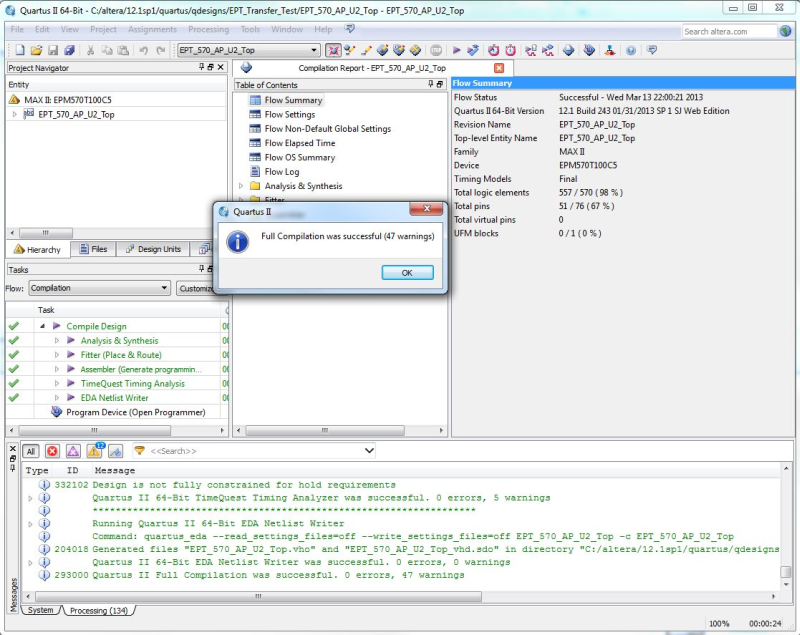
| The included Windows development environment kit includes: Quartus Prime Lite for compiling user code, assigning pins, project setup, programming and other items. The kit also includes the EPT ActiveHost core for the DPL, to facilitate communication between the PC and DPL while the DPL is running a developed project. The kit also EPT has developed a .dll that allows Quartus Prime Lite to directly program the DPL in the same way USB-Blaster works with other Intel/Altera populated development boards. |
|
Configuring the FPGA
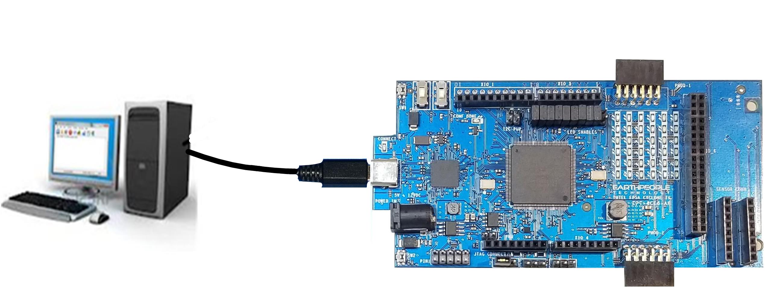
| The FPGA on the DPL can be programmed with the HDL project created by the user. Configuration is quick and easy. All that is required is a standard USB cable with a Micro Type B connector, and the EPT Blaster Driver DLL installed on the PC. There are no extra parts to buy - just plug in the USB cable and connect the DueProLogic to the PC. |
| The DPL Configuration Flash is programmed using the Quartus development environment and the EPT Blaster Driver. Once the the Configuration Flash is programmed. A reset will cause the FPGA to begin configuring itself using the Flash. |
| The board comes preloaded with Blinky, the test that each board goes through before being shipped with conductive foam in a static-control bag. Also included with the product is a DVD with the needed PC/Quartus/DPL drivers, library, User Manual, Schematics, and sample projects, which are also available on the EPT web site. To save expense and possibly the environment, and because many purchasers already have a micro-USB data cable, one is not included. |
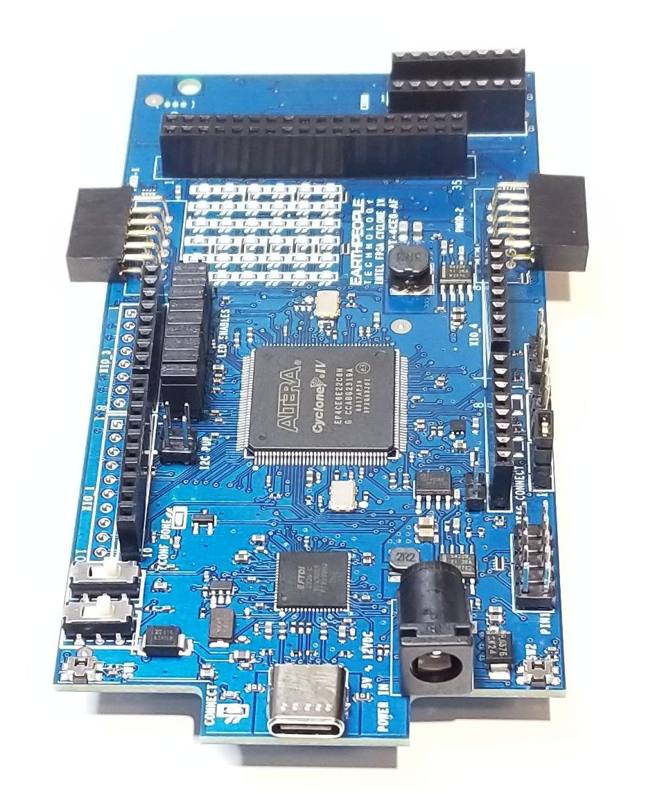
| Specifications: Designed to be stand-alone and/or be mated with an Arduino Due. Designed to be inserted directly into a standard breadboard, for easier prototyping Designed with the Arduino Due shield header layout, to accommodate 3.3v-compatible Arduino-type shields, plug-in modules EPT offers, or modules you might develop using standard 0.1” pitch single or double row pin headers. Designed and assembled in the USA and made to be RoHS (no Lead) compliant around the world. The DPL is made to accept standard USB Micro B cable connection and power input of 5-15VDC, but the header logic pins are only 3.3V compatible, like most other high-speed products using today’s chips. Applying 5V to a pin connected to the FPGA chip will cause permanent damage to the FPGA chip. |
DueProLogic Features:
|
Downloads
| 85-000012 | DueProLogic FPGA Development System User Manual | DPL_FPGA_DEV_SYS_UM.pdf |
| 95-000012 | DueProLogic FPGA Development System Data Sheet | DPL_FPGA_DEV_SYS_DS.pdf |
| 45-000012 | DueProLogic FPGA Development System Project DVD | DUEPROLOGIC FPGA PROJECT DVD |
| 55-000012 | DueProLogic FPGA Development System Schematics | EPT-DPL-USB-FPGA-SCHEMATICS.pdf |
| 35-000001 | EPT Drivers | EPT_2.08.24.ZIP |
Sorry, the comment form is closed at this time.